|
PUMP UNIT
Устройство и работа форсунки DAF XF 105
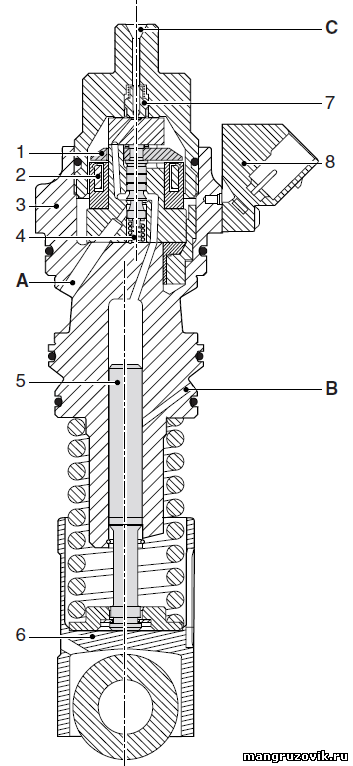
General The pump unit supplies fuel to the injector. The pump unit consists of a metal housing (3) in which an electrical coil (2) opens a valve (1). In the rest position, the valve (1) is pushed up by a spring (4). The electrical connection (8) is screwed onto the outside of the pump unit. The roller tappet (6) rotates around the camshaft and actuates the plunger (5), which builds up the fuel pressure. The fuel enters the pump unit via the fuel gallery opening (A). This opening goes into the fuel supply gallery in the engine block. The fuel leaves the pump unit in the direction of the injector via a delivery valve (7). The fuel pipe is fitted to the injector supply connection (C). Leakoff/ lubricating fuel from the plunger is fed back to the return gallery in the engine block via the return opening (B).
A. Fuel gallery opening B. Return opening C. Injector inlet connection 1. Lid 2. Coil 3. Pump unit housing 4. Spring 5. Plunger 6. Roller tappet 7. Delivery valve 8. Electrical connection
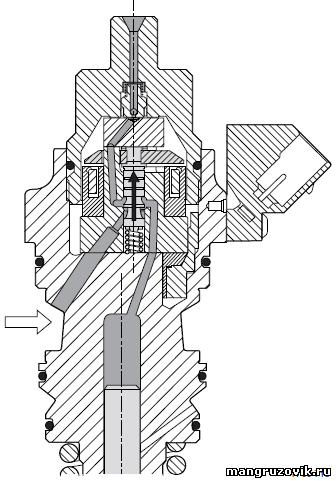
Electrical control The pump unit is activated with a voltage of approximately 50V. This voltage is the discharge from a capacitor in the DMCI electronic unit. The current increases rapidly because of this relatively high voltage. As a result, the valve in the pump unit opens quickly. This is the pick-up phase. If the current were not limited, it would become too high and damage the coil in the pump unit. The increase in the current is limited by switching to pulsating control of approximately 24V after discharging the capacitor. This is the withstand phase. The current now remains high enough to hold the valve open. The length of the pick-up phase stays practically the same under all circumstances. The length of the withstand phase will vary depending on the calculations carried out by the electronic unit. When the pump unit is deactivated a negative induction peak is created by switching off the current through the pump unit coil. Operation The fuel is supplied to the pump unit via the gallery in the engine block flowing towards the delivery chamber above the plunger. The delivery chamber now fill. остальной материал по ремонту DAF |