|
XF105 series Описание топливной системы DAF XF 105 гидравлическая схема топливной аппаратуры SYSTEM DESCRIPTION OF FUEL SYSTEM
Fuel system
КАРТЫ УСЛОВНЫХ ОБОЗНАЧЕНИЙ НА ГИДРАВЛИЧЕСКИХ СХЕМАХ УСЛОВНЫЕ ОБОЗНАЧЕНИЯ ЭЛЕМЕНТОВ ГИДРОПРИВОДА
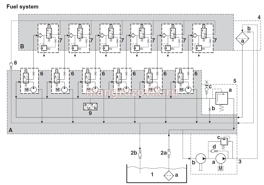
A- Cylinder block B- Cylinder head 1- Fuel tank 1a- Fuel-tank coarse filter 2a -Shut-off valve, supply 2b -Shut-off valve, return 3- Fuel pump 3a- Lift pump 3b- Primer pump 3c- Pressure release valve 3d -Circulation valve 4 -Fuel filter 4a- Filter element 4b- Bleed restriction 5 -Fuel pressure control valve 5a -Pressure control flap 5b- Throttle bleed/idling speed 5c -Fuel pressure measuring point 6 -Pump units 7- Injectors 8- Non-return valve 9- Fuel pressure and temperature sensor
The fuel lift pump (3a) draws fuel out of the fuel tank (1) via a shut-off valve (2a) in the supply pipe. The fuel goes to the fuel pump (3) via the cylinder block (A). The fuel lift pump (3a) pumps the fuel via the fuel filter (4) to the fuel gallery in the cylinder block (A). The pressure in the fuel
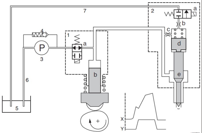
Fuel filter There is a coarse filter (1a) in the fuel tank (1),which prevents any larger impurities from the bottom of the fuel tank getting into the fuel lift pump. From the fuel lift pump, fuel is pumped to the fuel gallery through the fuel fine filter (4). The fuel filter is self-bleeding. There is a throttle (3b) at the highest point in the fuel fine filter (4) through which air in the system is discharged to the fuel tank. Basic function of injection The pump unit and injector work in tandem to bring about fuel injection. A complete fuel injection cycle is described in the following steps.
Filling The fuel lift pump (3) draws fuel out of the tank (5) via the inlet pipe (6) and pumps it to the pump unit (1). The pump unit has not been activated and the pump unit valve (1a) is open. The space above the pump unit plunger (1b) is filled. Because the camshaft moves the pump unit plunger up, the fuel can now flow back to the supply side. Pressure has not yet built up in the fuel injection pipe. остальной материал по ремонту DAF DAF 95 XF электрическая схема DAF XF 105 электрическая схема управлением двигателя ECU DMCI
|